
Building Guide
This guide provides the basic steps for building your model.
Please follow each step carefully and refer to the images for additional guidance.
Required Tools
To ensure proper assembly of the model, the following tools and materials are recommended:
- Screwdriver
- Drill with 1.2mm drill bits
- Pliers
- Long-nose pliers or tweezers
- Thick CA glue (cyanoacrylate) with activator
- Sandpaper (120-180 grit)
- Epoxy adhesive or epoxy resin
- Mini grinder / rotary tool (e.g. Dremel)
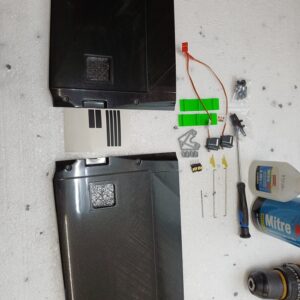
Included Materials
Each model is delivered with a set of auxiliary materials required for assembly.
- Peg
- Pull strings and control horns
- Servo trays from fiberglass
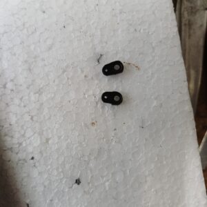
- Spring connectors
- Templates for connector alignment
- Screws for attaching the wings and tails to the body
- Other necessary hardware for completion – caps, vinyl pads, stickers for the caps, ballast tray
- Angle gauge

Shaman 2

Shaman Evo
Wing Servo Installation
The installation of wing servos is identical for all models.
Follow the steps below for proper installation of the wing servos and linkages.
Step 1 – Surface protection
Apply the included PVC protective film to the working area of the wing.
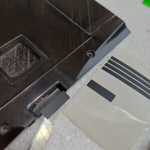
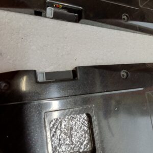
Step 2 – Spacer Installation
Position the spacer and secure it with a small drop of CA glue.
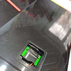
Step 3 – Servo Mount Preparation
Drill holes in the servo tray using a 1.2mm drill bit.
For KST servos, use only the raised sections of the tray due to the larger servo size.
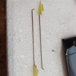
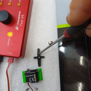
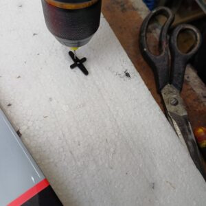
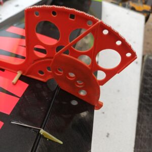
Step 4 – Servo Arm Preparation
Prepare the servo arms using the hole shown in the reference image.
- Drill the required hole
- Trim the excess material.
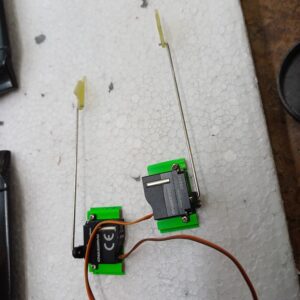
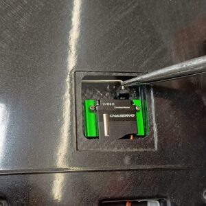
Step 5 – Servo Positioning
Reinstall the servo arm
The servo arm should be offset by one spline from vertical, in the direction of flap deflection.
This ensures full servo travel.
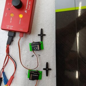
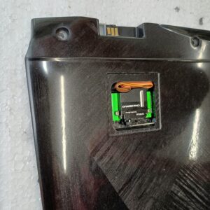
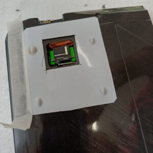
Step 6 – Neutral Position Setup
Install the servo and check alignment using the angle gauge.
At neutral servo position:
- the aileron should be deflected 12-15 degrees.
Once confirmed, glue the control levers using thick CA or epoxy.
Step 7 – Servo Fixing
With the aileron deflected to 15 degrees and the servo at neutral, fix the servo tray in position.
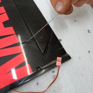
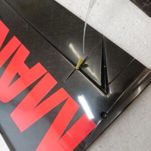
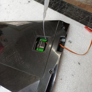
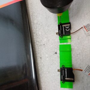
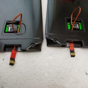
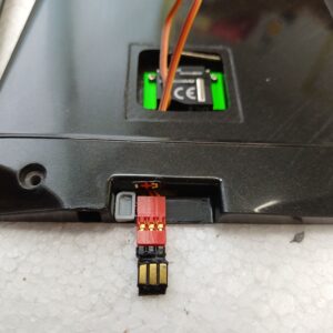
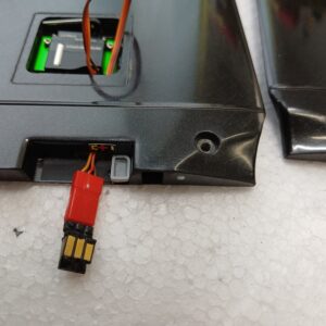
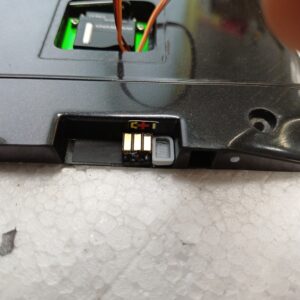
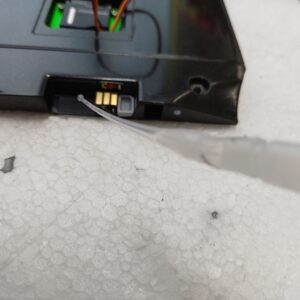
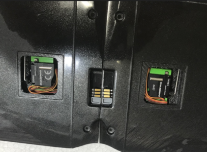
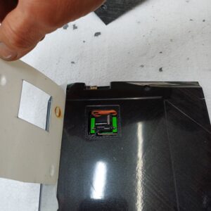
Step 8 – Connector Installation
Install the connectors at the end of the cable, ensuring correct orientation.
After testing, secure them to the spacer with a small drop of CA glue.
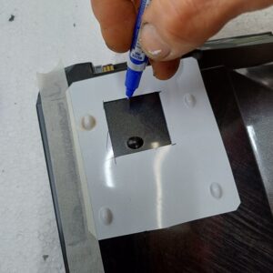
Step 9 – Servo Cover Tip
For easier installation of the servo cover:
- Cut a window in a piece of rigid cardboard matching the size of the cover.
- Use it as a template to cut the cover from the included carbon sheet. You can use scissors for this.
After final assembly, the cover can be fixed using the included branded sticker.
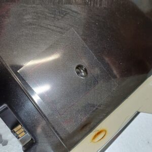
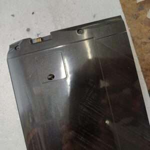
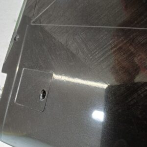
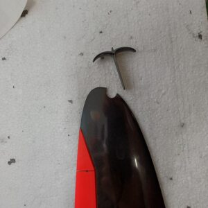
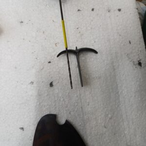
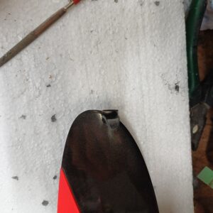
Step 10 – Launch Peg Installation
Carefully cut along the marked contour on the wing
Remove the core material carefully, without damaging the surrounding structure.
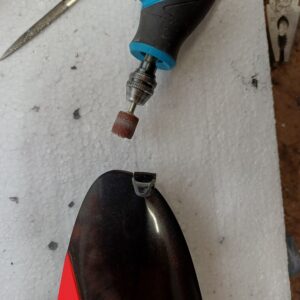
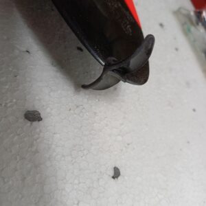
Check the fit of the launch peg.
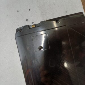
If necessary, adjust the opening using a mini grinder until the peg fits properly.
Glue the peg in place using epoxy resin.
Ensure proper alignment before the adhesive cures.
Make sure the peg is aligned correctly for comfortable launch grip before the epoxy fully cures.
Step 11 – Spoiler Tape Installation
The spoiler tape is included in the kit and may be installed if desired.
A small amount of talcum powder is required. Place the wing on a flat, rigid surface with the ailerons slightly deflected downward. Lightly dust the upper edge of the aileron with talcum powder to prevent unwanted adhesion.
Apply the tape carefully along the lower side of the wing.